Briefly Describe the Coordinate System Used in 3d Modeling.
Let us assume that the original coordinates are X Y Z scaling factors are S X S Y S z respectively and the produced coordinates are X Y Z. Typically the viewport will occupy the entire screen window.
Datums Projections And Coordinate Systems Mar 2017 Cseg Recorder
ABSOLUTE COORDINATE ENTRY Absolute coordinate entry is the default.

. Figure 61 shows a. There are different coordinate systems Cartesian polar etc and you can transform coordinates from one system to another. The anatomical coordinate system is a continuous three-dimensional space in which an image has been sampled.
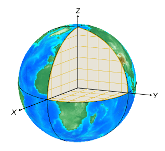
3D Space In order to represent points in space we first choose a fixed point O the origin and three directed lines through O that are perpendicular to each other called the coordinate axes and labeled the x-axis y-axis and z-axis. Thats to say it does not affect objects within the coordinate system unlike left-handed vs right-handed it simply affects how we interpret the coordinate system. The origin of the virtual universe is the intersection of the 3 axes.
In a three dimensional Cartesian coordinate system we simply add a third axis z that is mutually perpendicular to both x and y. A coordinate system is a system which employs one or more numbers that is one or more coordinates to uniquely specify the position of a point. There are two popular choices for the up axis.
In hierarchical modeling an object can be defined in its own natural coordinate system usually using 000 as a reference point. The points coordinates are defined in regards to the cameras coordinate system. Believe it or not by giving these three locations5 blocks north 3 blocks east and the third flooryouve just employed a bit of mathematics to define whats called a coordinate system and to give your locationyour coordinatesin it.
Type L on the command line and press enter Type 46 on the command line and press enter Type 53 on the command line and press enter. This can be mathematically represented as shown below. For example it is usual to build a model in its own modeling frame and later place this model into a scene in the world coordinate frame.
In geometry a coordinate system is a system that uses one or more numbers or coordinates to uniquely determine the position of the points or other geometric elements on a manifold such as Euclidean space. In neuroimaging it is common to define this space with respect to the human whose brain is being scanned. With AutoCAD Map 3D toolset you can combine data from maps using different coordinate systems.
Its point is 0 0 0. 3D coordinates are used for example by air traffic controllers to find the location of a plane by its height as well as its grid reference. Coordinate Systems The idea of a coordinate system or coordinate frame is pervasive in computer graphics.
You can remember which direction the positive z-axis points by pointing the fingers of either your left or right hand in the positive x-direction and curling them. To implement this we need a way of limiting the effect of a modeling transformation to one object or to part of an. By convention we use the z axis to be the vertical direction in three dimensions.
When drawing lines AutoCAD is ready to place the next vertex wherever you tell it to go. Coordinate Systems for Modeling Modeling aircraft and spacecraft are simplest if you use a coordinate system fixed in the body itself. In 3D scaling operation three coordinates are used.
The order of the coordinates is significant and they are sometimes identified by their position in an ordered tuple and sometimes by a letter as in the x-coordinate. We will use the Cartesian coordinate system. The vector OP has initial point at the origin O 0 0.
In both coordinate systems the positive x-axis points to the right and the positive y-axis points up. Typically 3D graphics applications use two types of Cartesian coordinate systems. We often refer to the modeling frame as the object frame and the world coordinate frame as the scene frame.
Each 3D model in the virtual world also has its own coordinate system which has its origin at the center of the object. In Vizard the linear unit of measurement is meters. Usually we think of the x- and y-axes as being horizontal and the z-axis as being vertical and we draw the orientation of.
Each point in space can be described by numbers called coordinates that represent its distance from this set of axes. This is the known as the world coordinate system. The position of an object can then be specified by using the three coordinates x y and z.
Once in camera space the points are then projected onto the. 1024x768 Viewport Coordinate System - This coordinate system refers to a subset of the screen space where the model window is to be displayed. In a 3D coordinate system the idea of up is purely semantic.
The Cartesian coordinate system made it possible to represent geometric entities by numerical and algebraic expressions. First point are converted from 3D world space to camera space. Screen Coordinate System - This 2D coordinate system refers to the physical coordinates of the pixels on the computer screen based on current screen resolution.
Hence the 3D basis is defined along the anatomical axes of anterior-posterior inferior-superior and left-right. To do this you specify the coordinate system used for attached drawings and for the current drawing. The object can then be scaled rotated and translated to place it into world coordinates or into a more complex object.
In the case of aircraft the forward direction is modified by the presence of wind and the crafts motion through the air is not the same as its motion relative to the ground. When you bring objects from attached drawings into the current drawing the objects are transformed to the coordinate system of the current drawing. We start from a point in 3D space which we need to somehow project on the image a process for which a perspective or orthographic projection matrix is generally used.
Absolute coordinate entry always counts from the origin. A 3D coordinate system adds a third axis referred to as the Z-axis that is perpendicular to the two other axes. If youre in the third floor coffee shop you need to give your friend that piece of information too.
Coordinate Systems
Coordinate Systems
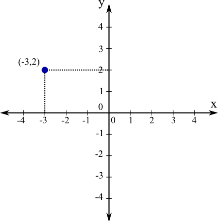
Cartesian Coordinates Math Insight

About Coordinate Systems Revit 2020 Autodesk Knowledge Network
![]()
Coordinate Transformations
Choose A 3 D Coordinate System Matlab Simulink
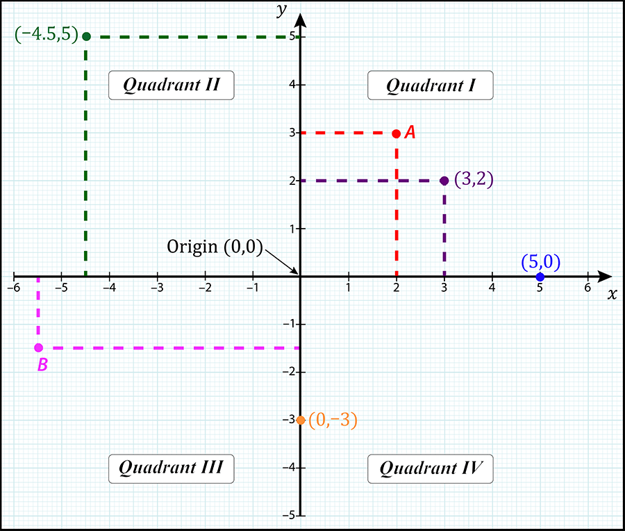
Introduction To Cartesian Coordinate Systems Skillsyouneed

2 Polar Coordinate System The Vector R Is Expressed In Terms Of Its Download Scientific Diagram

Point Charge Represented In 3d Cartesian Coordinate System Download Scientific Diagram

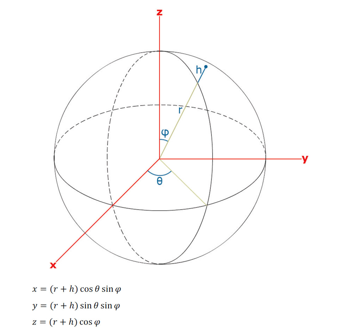
The Spherical Coordinate System Where 8 0 P Is The Polar Angle Download Scientific Diagram

Rectangular Coordinate System An Overview Sciencedirect Topics
Coordinate Systems
Right Handed Coordinate System

Point Charge Represented In 3d Cartesian Coordinate System Download Scientific Diagram
Coordinate Systems

Coordinate Systems In Autocad Ourengineeringlabs
Coordinate Systems

Coordinate Systems For Navigation Matlab Simulink
Intro To Computer Graphics Coordinate Systems


Comments
Post a Comment